EARTH TO MOON SHUTTLE - “AURORA”
Pre-planning
an Essential Necessity!

The “Aurora”, an Earth to Moon Shuttle – or ETM Shuttle, was a design that floated around in my head for quite a while. A necessary vehicle for my next epic motion picture, working title, “Anniversary”, it needed to launch vertically and travel to the Moon. A friend had given me a 1:72 scale Russian “Backfire” aircraft a couple of years ago, fully assembled and awaiting the paint job. Being unhappy with it, he had passed it on to me in the hope that I may be able to do something with it. Quite a large model it was too, with an impressive wingspan, however a few parts were missing such as the undercarriage doors, although they could be in my collection of parts in the shed. Stranger things have happened in my shed! So there it sat on a shelf for a number of years until a couple of other kits fell into my lap, namely a pair of 1:48 scale “Thunderbirds” F-100 aircraft. All of a sudden inspiration struck and off I went! Halfway through this project I needed some additional inspiration so I visited one of my favourite sites – Space Models Photography, operated by Keith McNeill in the UK. His scratchbuilt Aurora photographs on its launch pad gave me the ideas I had been seeking. His wonderful site can be found at:


With
my trusty hacksaw I removed the main wings, tail fins and vertical stabiliser
from the “Backfire”, leaving me with a bare form that I could mate the F-100
fuselages to on either side.


The fuselage was carefully prised apart and work
began from the inside out, installing all the lights that I thought would give
a nice look to the finished shuttle. A small, 3mm high intensity LED was
installed in the cockpit, just in front of the pair of pilots who came from the
spares box. Being quite small at 1:72 scale, they were glued directly into
their seats without any further additions as very little of them would be seen
from the outside, just the red glow and some vague human shapes. The canopy
covering the cockpit area was carefully cut with a razor saw to form a new
viewport area, a simple arched window which was “glassed in” from behind with a
thin acrylic sheet. Ribbed sheet became the anti-glare panel in front of this
viewport. A flashing LED was installed atop this nose section and the wires
joined to those trailing from the cockpit LED. After trimming the sharply
angled side intakes to a different look, some scribed sheet was glued to the
leading front indentation, along with plain styrene sheet to cover over the
surrounding areas. To facilitate certain filming angles which would occur many
months later, a lot of internal planning was carefully thought out before
joining the two halves of this front fuselage area together. A 7mm section of
brass tube was inserted through the lower half of the cockpit area, under the
pilots’ seats and firmly glued into position, while a length of heavy gauge
wire was looped and glued alongside the tube. The wire loop would allow me to
suspend the model for the launch scene and the tube would be used as a mounting
point to suspend the vehicle from the nose. The pointy nose of the original
“Backfire” had been sawed off at this stage. A new undercarriage cover was
quickly cut from styrene sheet and glued into place. With one pair of trailing
wires dangling from the rear, the front section was basically finished.


I
knew I wanted an upper wing assembly for the shuttle which would be securely
glued to the tops of the three aircraft fuselages, so I went about creating two
of them from sheets of 2mm styrene. After roughly cutting them out and trimming
them, they were secured together temporarily with superglue and carefully
sanded as a pair to ensure that both were identical. On the lower half I added
some Evergreen square tube around the perimeter, leaving a 5mm gap around the
edges, along with extra strips down the middle to add strength and support to
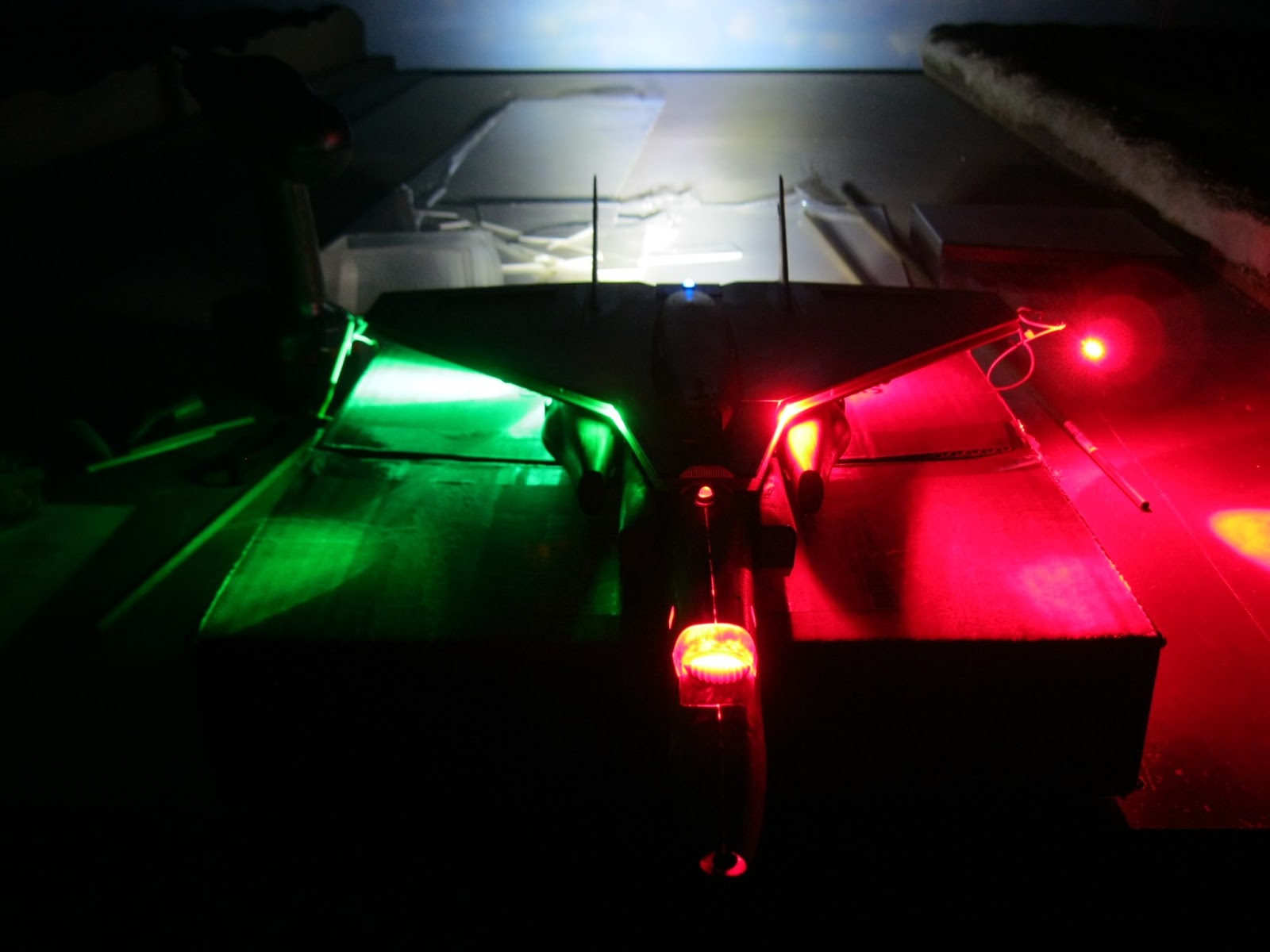
the wing. More red and green 3mm LEDs were added to this section as well, red
on the left and green on the right of course. A late addition was the drop tank
half and rear landing gear cover that I cut from a swimming goggle container of
all things. Styrene rectangles became the bogus doors for this landing gear. On
the upper half I needed some interesting detail areas so I removed a pentagonal
section from both sides and backed it with two pieces of styrene sheet that I
scored parallel lines on myself. Down the centre of the upper wing half sits
the 1:200 scale (I think) hull of a ship that I located in a box somewhere. The
bow was trimmed back at an angle and backed with a small piece of ribbed
styrene to represent an intake grill. It may not be completely logical, but it
definitely looks better with it added. Another 5mm flashing LED was added to
the rear, with the wires leading down through a hole in both the upper and
lower wing sections. Because I intended adding large ion engines to the outer parts
of both wingtips, additional wires were fed through holes to join up with this
flashing LED. These wires would later power another pair of red and green LEDs
to be positioned on the outer sides of the ion engines used for travel in space.
The ion engines themselves were purchased in a pack of three LED torches that
were powered by a trio of AAA batteries and boy, are they bright! As I wanted
four ion engines in all, I had to buy two sets of torches at $15 each – a
bargain as the extra torches would be used on another model project in the
future.


I
assembled the F-100 fuselages temporarily with masking tape, along with the
front intakes and rear exhaust ports, and installed red and green LEDs on the
top of each, as well as 5mm high intensity white LEDs for the engines. Luckily
the F-100 kits had come with alternate engine exhausts as these had been added
to the fuselage of the “Backfire” as additional rocket engines, making a total
of four in all. These white, high intensity LEDs were extremely bright, in fact
very difficult to look at directly, although at about $6 each, they were quite
expensive but very necessary to achieve a good engine glow. Araldite, the
two-part epoxy, was used to glue the lights into position. Originally I had considered
pumping smoke through the engine exhausts to simulate liftoff, however after
many attempts to make this work on such a small scale, I opted for just the
engine glow instead, relying on inspiration and shooting angles to achieve a
satisfying liftoff for the video camera. Both canopies were glued into position
and then I sanded furiously for a number of hours to remove any vestiges of the
many raised panel lines present on the fuselages. The rear tail wings were
removed, landing gear covers installed and any large gaps covered over with
strips of styrene, after which the two halves were securely bonded with
Araldite. The vertical stabilisers from both kits would be added to the top of
the wing assembly at a later date.


In
order to mate all three fuselages together firmly, I used Araldite liberally,
firmly gluing the F-100s to the upper fuselage section of the “Backfire”. For
additional strength and to provide two more mounting points for the model, I
cut holes and inserted a length of square brass tube right through the three
fuselages, secured with Araldite and car putty. As I was unsure what the final
weight of the model might be and where its centre of gravity lay, I resorted to
using the square tube instead of the previous round sections so that the model
would not swing around whilst filming it. Smaller brass tubing, topped with a
styrene cap, telescopes into this larger piece snugly and hides the mounting
points on either side of the fuselage. An additional hole was then drilled
vertically through the “Backfire” fuselage, as well the wing assembly, to
install yet another 7mm brass tube which extends from top to bottom and
provides two more mounting points for the model, making a total of five in all
– in the nose, both sides of the fuselage and both top and bottom. The pair of
vertical stabilisers came from the F-100 kits, left as is except for a couple
of short lengths of narrow brass tube inserted into the base of each to firmly
anchor them to the upper wing surface.


To power all the lights in the final model,
fourteen in all, two battery boxes had previously been constructed in the lower
half of the fuselage. Rectangular styrene covers for the battery boxes were cut
out. These would be fixed, temporarily, with superglue. Small slide switches were
installed within the open rear landing gear recesses and all the wires had to
be routed through the model to connect up with the switches and battery boxes,
a daunting undertaking considering the number of them and the layout of the
lights. I thought I had plenty of room inside the “Backfire” fuselage, however
with the two battery boxes, two switches and all the wires, it turned into a
sort of nightmare to co-ordinate. When it was all organised, the lower half was
Araldited firmly to the rest of the fuselage. Sheet styrene pieces were used to
conceal the resulting holes and gaps because the wings had been removed.


For
the side-mounted ion engines, powered by a quartet of LED torches, I had
originally considered using a section cut from a plastic kitchen container
which seemed an ideal shape. As I had one of them, then it seemed feasible to
be able to locate a second one fairly easily. No luck at all. I searched and
searched in vain and had decided to vacuform two sections from the one original
I had, however the resulting shapes would have been far too thin and flimsy to
act as the engines, especially with the weight of the torches, so the hunt was
on once more. At a local K-Mart I spotted some plastic, litre measuring jugs
for just $2 each. After purchasing three (just in case a mistake was made), I
took them home and proceeded to mark one of them up in permanent pen to form
the half-cylindrical shapes I needed. A stroke of luck ensued when I spotted an
interesting shape at the local recycling centre in the form of a food pusher,
used to shove edible items into a kitchen processor. After a fruitless search
trying to locate a matching partner, I resorted to carefully cutting the one I
had in half.


These basic shapes were strengthened with sections of 2mm styrene
at the rear where two holes were cut, both about 34mm in diameter, to accept a
pair of PVC plumbing pipes which the torches slid into quite comfortably. These
two tubes ran half the length of each engine, firmly cemented into place with
Araldite and car putty.


The torches slide into the tubes, allowing me to turn
them on and off at will for filming purposes. Being quite heavy, the torches
will have their trio of AAA batteries removed until they are needed to fire up
the ion engines for the video shoot. Scribed plastic sheet was added to the
front of each ion engine to form an intake, while some Evergreen strip was
wound around the leading edge to provide a necessary recess. A red and green
LED was also added to each respective outer side of the engines, the wires
already present and protruding from the wingtips that the engines would be
fixed to. To secure the engines to the wings, Evergreen square tubing formed
the bracing to secure them in position.


Following a lengthy bout of sanding and filling, the shuttle was finally ready for painting. I primed the entire model with several coats of good quality acrylic car primer, followed by another round of sanding with very fine steel wool to achieve a smooth finish.


The colour scheme I had chosen to do consisted of a few light base coats of Vanilla White, after which the entire model was masked off and certain areas were sprayed in Metallic Polaris Blue, including the ion engines, shuttle underside and the wingtop recessed areas. Gunmetal was used on the four rocket engine areas and the ion engines, ie. the protruding ends of the LED torches. The leading edges of the wing and the pair of vertical stabilisers were carefully handpainted in Tamiya Flat Red, along with the seven intakes areas. Using a fine, permanent black pen, I added a myriad of panel lines to the whole surface of the model, tracing carefully along a steel ruler and a narrow piece of thin acrylic to achieve the lines on the curved sections. Generic decals from the spares box were added to various areas of the model, followed by a round of coloured pinstriping tape which had been trimmed to half of its 3mm width. With a 2B pencil I sanded the tip until a small mound of graphite resulted and carefully smudged some of this to produce a panelling effect over the model, using a piece of paper to achieve the straight edges. A number of matt clear coats protected the paint, tape, decals and graphite panelling. The "Aurora" name and Earth to Moon symbol were created in the computer and printed out on decal sheet, after which the new decal was sprayed with a clear coat to protect them.


With
five separate mounting points, fourteen LEDs, four AA batteries, two switches
and quite a length of wiring, the “Aurora” shuttle is finally ready to transport
passengers from a launchpad, all the way to an orbiting platform near the moon,
and then return to Earth, soaring down through re-entry, to land like a
conventional aircraft. I’m quite happy with the resulting model. Even though it
took quite a bit of time and additional work, not to mention making a couple of
mistakes along the way, the lights were certainly worth the effort and add that
something extra to the model during photography. I’m hoping that it will
perform just as well for the video camera in the near future.
More completed photos will follow after I construct the Launch & Assembly Building (LAB) and the launch pad itself, both of which are sizeable undertakings, the LAB itself being about 60cm in height. (Many thanks, once again, to Keith McNeill for allowing me to copy his interesting design for the LAB).
Take care and keep on modelling!